Before you begin
Welcome to my tutorial on how to create collapse models for Red Alert 3. First things first: this tutorial utilizes a Max script I wrote to auto generate needed XML code, so before you begin, you’ll need to download it by clicking here. You can put the script wherever you want; however, MaxScripts are generally put in the [3DS Max directory]\Scripts folder. Start up 3DS Max and in the toolbar, go to MAXScript > Run, navigate to where you put the script, and run it. Alternatively, if you put the MaxScript in the [3DS Max directory]\Scripts\Startup folder, then the script will be executed on startup and you won’t need to manually run it.
This type of script is called a Macro script, which means it is launched from the tool bar, so you must now customize your 3DS Max tool bar to include the script. To do this, in the tool bar go to Customize > Customize User Interface. In the new window that opens, go to the ‘Menus’ tab. By default, Main Menu Bar is selected on the right; although you’re free to put the script where you want, I recommend putting it somewhere in the Main Menu bar; personally, I put it under the Tools menu. Find the script from the list of actions listed on the left - it’s in the category “Calculator,” which isn’t a normal 3DS Max category, so it should be the only one listed there. Drag the script from the Actions on the left to a menu location on the right, and it should now appear under that menu in Max and you’re ready to use it.
Getting Started
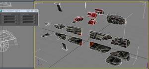 Now it's time to start setting up the actual collapse model. This tutorial is not about how to model in 3DS Max, so I'm going to assume you have some Max skills at this point. Starting with your model, subdivide it however you wish into "chunks" of rubble, and separate them. In order to speed up the making of this tutorial, I simply used quick cut to slice the model into pieces. The best way to separate the chunks is to use the Move Transform Type-In dialog box which you can open by right-clicking the Select and Move button at the top of the screen. I recommend using an easy number to remember for each of the chunks, like a multiple of ten. I also recommend setting the Reference Coordinate System to “World” instead of “View” so that the chunks will move along the axis you are typing in regardless of which viewpoint you have selected.
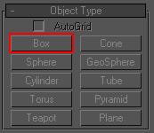 After you’ve divided the debris how you want it, select the Box primitive and create a box in the top view. You’ll be using Box primitives as bones; the script derives volume information from the name and properties of the Box primitive. DO NOT change the Box into an Editable Poly or mesh or else the script will not work.
Select a chunk of debris to start with and move and rotate the box as well as modify the Box’s Length, Width, and Height properties in the Modify tab to approximately fit the box around the chunk of the debris. DO NOT use the ‘Select and Scale’ tool to modify the shape of the Box, this will not work with the script.
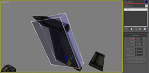 You also want to give the Box a name. This name will be used as the bone name in the code. I recommend using a name that gives you an idea of what part of the debris this bone is bound to; this will be useful later. For me, I use the following convention to name bones: first, I start all bone names COL_ (this way all the bones used for volume bones will be grouped together in object lists); next I give it a name that tells me what it is, in the pictured example: FIN_ (this lets me know this is one of the fins of the model); finally I end the name with 01. In Max, when you clone an object (by holding ‘shift’ when you move it), Max will automatically increment the number at the end of the name. In this model there are four fins, so when I clone the volume to form the collision bone for the next fin, Max will auto name it COL_FIN_02.
 You may notice the material I have on the box in the picture. Because the geometry of the box won’t be exported with the model, you may put whatever material you want on the Box primitives being used as bones. I recommend a semi-transparent material. Repeat this process so that every chunk of debris has a Box primitive around it.
Skin it
Now it’s time to skin the model. Drop a WWSkin object into the scene and add all the collision bones to the bone list. Bind the model to the WWSkin object with the Bind to Space Warp tool. Then simply bind each chunk of debris to its correlating bone. Again, this tutorial assumes you have some knowledge of how to use Max and the Westwood tools so I’m not going to go into detail about how to do this.
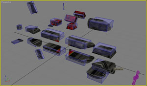
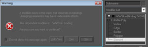 After you’ve bound all the debris to a bone, you’ll want to start putting the model back together. With your model selected, go to the Modify tab and select Editable Poly from the modifier list and select the element sub-object. You should get an error message like the one in picture warning you that editing things lower in the modifier stack may break things higher in the stack. As long as you only MOVE vertices, and don't add or remove any, you should be fine. Select ‘Yes’ or ‘Yes/Hold’ to continue. Now you’re going to do in reverse what you did in the beginning and move all the chunks of debris back together; again, I recommend using the transform type-in tool, and using the same values as when you separated them.
Once you’re done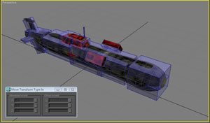 , deselect the model. Now you’re going to move each of the bones to where its correlating piece of debris has been moved. Once again, I suggest using the Transform Type-In dialog and use the same values as before. Don’t forget to make sure Reference Coordinate System is set to ‘World’. After you’ve done all this, you may wish to test to make sure something hasn’t gone wrong and the bones haven’t become detached from their respective piece of debris.
Exporting
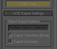 Now it’s time to set up and export the model. First select the model and go to the W3D Tools in the Utilities tab. The default settings are fine, but in case you’ve changed from the default: both the Export Transform (bone) and Export Geometry checkboxes should be checked. ‘Geometry Options’ should be set to normal. Now select all the Box primitives you’re using as bones and again go to W3D Tools under the Utilities tab. By default ‘Export Geometry’ is checked, uncheck it; you only want to export the bone. That’s all the Export setup that needs to be done, now simply export the model as a .w3x. You can give the model any name you want, however the standard naming convention of RA3 is typically the unit/structure name suffixed with _COL. Export it as a Hierarchal Model.
Now we get to use the MaxScript. Select all the Box primitives you’re using for a bone volume and then select to run the script from whatever menu you placed it in. I didn’t initially write this script with the intention of releasing it to the public, so it only has two methods of error checking: one to see if you’ve got anything selected at all and one to make sure all the selected items are Box primitives. If either condition is false you should get an error message. When you run the tool, a save file dialog box will come up. It will save as a text file and it doesn’t matter where you save it or what you name it as long as you can find the file; you’ll have to copy and paste the code from the generated file into the correct location in the xml files. After you save the file, you can close Max.
Coding
The first bit of coding you’ll need to work with is the code file we just generated, so find the code and open it in whatever code text editor you use. Most of the code is auto generated however there is one field that is using a default value: “Spinniness”. You’ll notice the first property field of each BoneVolume code is ‘BoneName’, this is why I said it would be a good idea to give the bone a name you’ll recognize so that you can properly determine what the Spinniness of each volume should be. Spinniness is almost always fine at 3.0, however you’re free to mess with it if you wish to give the piece of debris in question more or less spin. Setting “Spinniness” to 0.0 will prevent this piece of debris from spinning at all, which you may want in certain situations. Mass is less intuitive and the values you’ll enter here are fairly arbitrary. The default is based on the volume of the Box primitive, but you may wish to change these if you feel the default isn't accurately representative of the piece of debris. Now put this aside for a minute.
<BoneVolume BoneName="COL_FIN_01" Mass="300" Spinniness="3.0" ContactTag="DEBRIS" >
	<Box HalfSizeX="3.74103" HalfSizeY="0.831795" HalfSizeZ="5.17804" >
		<Translation x="-34.2624" y="-6.85855e-007" z="7.79638" />
		<Rotation x="0.0" y="-0.21644" z="0.0" w="0.976296" />
	</Box>
</BoneVolume>
The next thing you need to do is set up the code in your vehicle/structure XML to use a collapse model. Assuming you copied the code you're using for your structure/vehicle, somewhere under the Behavior module you should find a module labeled “CreateObjectDie”. If not, you’ll have to add it. The CreateObjectDie module calls an Object Creation List when the structure/unit is killed. The typical naming convention for the OCL item is [OBJECTNAME]_Die_OCL (example: AUMediumTank_Die_OCL); this is the name you’ll have to refer to in the ObjectCreationList, which is where we’re going next.
<CreateObjectDie
         id="ModuleTag_CreateObjectDie"
         CreationList="-OBJECTNAME-_Die_OCL">
         <DieMuxData
                  DeathTypes="ALL" />
</CreateObjectDie>
Now you need to set up a new OCL in the ObjectCreationList. I highly recommend copying an existing OCL of the same type of object as the one your making (i.e. if you’re making an aircraft, copy the OCL from an existing aircraft, if you’re making a structure, copy the OCL from an existing structure). The ObjectCreationList module contains a number of properties, which you may wish to play with sometime, but the only one that you need to adjust is Collapse model referenced in between the <CreateObject> tags. The typical naming convention for this is [FACTION][OBJECTNAME]_Collapse (example: AlliedMediumTank_Collapse).
<ObjectCreationList
         id="-OBJECTNAME-_Die_OCL">
         <CreateObject
                  Options="IGNORE_ALL_OBJECTS"
                  Disposition="LIKE_EXISTING INHERIT_VELOCITY"
                  Count="1"
                  VelocityScale="15.0"
                  MinForceMagnitude="1.0"
                  MaxForceMagnitude="2.0"
                  MinForcePitch="90d"
                  MaxForcePitch="75d">
                  <CreateObject>-FACTION--OBJECTNAME-_Collapse</CreateObject>
         </CreateObject>
</ObjectCreationList>
Now it’s time to make the Collapse object code. Start by copying an existing _Collapse.xml file from an object of the same type you’re creating. Change the properties, such as id, EditorName, Includes, and the Model Name as necessary to reference the Collapse Model you exported. Now go back to the code you auto-generated from Max and copy it. Paste it in between the two <BoneVolumes> tags, replacing any BoneVolume modules there from whatever file you copied.
And that should do it. Now compile the mod, and blow stuff up!
Navigation